The ground reference defines how the ground of your Component is connected to your circuit. There are four types of ground reference: Floating, Sonnet Box, and Polygon Plane, and Polygon Edge.
NOTE: The Ideal Component does not use a ground node connection by definition. The ground node connection needs to be specified for all other Component types.
Sonnet uses a common ground for all the Component ports associated with a given Component. This common ground should model as closely as possible how your component was measured or modeled. Vendors who supply components often have measured S-parameters or a model which may be used to create S-parameters. In either case, information about how these values were obtained should also be available. Use this information to guide your choice of ground node connection. The four types of ground node connection are discussed below. You may also select "Auto" and allow the software to determine the ground reference.
When your ground reference is set to Box Cover, all the Component ports are globally grounded to the Sonnet box. To accomplish this, a via is automatically created which connects to the top or bottom of the Sonnet box. This option should be used if your component model, or measured data, includes shunt elements and you want the Component’s ground reference to be connected to the Sonnet box.
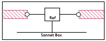
Examples of this are:
The analysis engine determines the most efficient direction the ground via extends taking into consideration both the distance and the loss of the box top or bottom. When using this type of ground, you must make sure that there is a clear path with no metal on other levels interfering with the path to either the box top or bottom.
If you are using a Component whose ground node connection is to the Box Cover, either the box top or bottom must have loss less than 50 ohms/sq. For example, you should not use “Free Space” as your box top and bottom definition. If the loss is too high on both the box top and bottom for a ground via from the Component to be attached, the analysis engine will issue an error message.
When your ground reference is set to Polygon Edge(s), the ground reference of your Component is connected to a polygon edge(s) selected by you when adding the Component. You may specify as many ground terminals as you need.
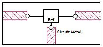
Examples of this are:
NOTE: The Polygon Edge(s) ground node connection is only available for Data File and Sonnet Project type Components.
When your ground reference is defined as Polygon Plane, the ground reference of your component is connected to a polygon above the present level, below the present level or both above and below the present level. The ground for the component is attached to the first polygon encountered in the direction specified for the ground reference. When using this type of ground, you must make sure that there is a clear path with no metal on other levels interfering with the path to desired ground plane polygon.
In addition, the polygon used as the ground reference must have loss less than 50 ohms/sq. If the loss is too high, the analysis engine will issue an error message. The polygon should also be large enough to be used as a ground plane. The metal polygon used as a ground reference is modeled as an infinite plane when the de-embedding is done by the analysis engine.
This type of ground reference is illustrated below.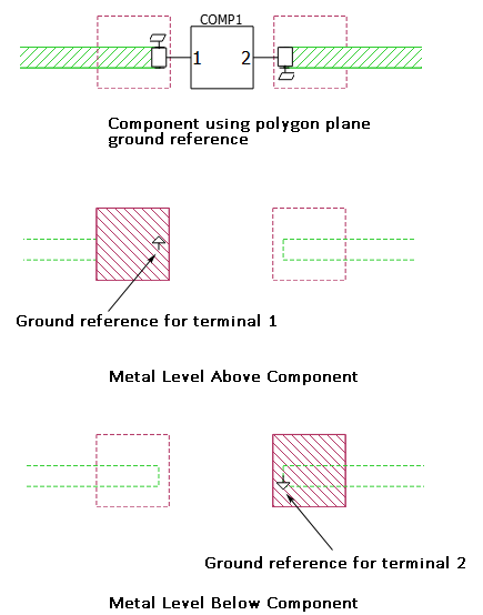
When your ground node connection is set to Floating, all the Component ports reference a common local ground as pictured below. This option should be used if your Component does not have a ground reference, or if there are no shunt elements in your component model or measured data. Any shunt admittance is removed by em.

Examples of this are: