It is important to note that calculating the transmission line parameters is based on the calibration standard. For box-wall ports, the calibration standard, as discussed in Calibration Standards, is based on a cross section of any metalization touching the box-wall, on all levels, that the port under consideration is on. This cross section is extended the length of the calibration standard. Since the cross section is taken at the box-wall, the interior of the circuit does not affect the basis of the calculation.
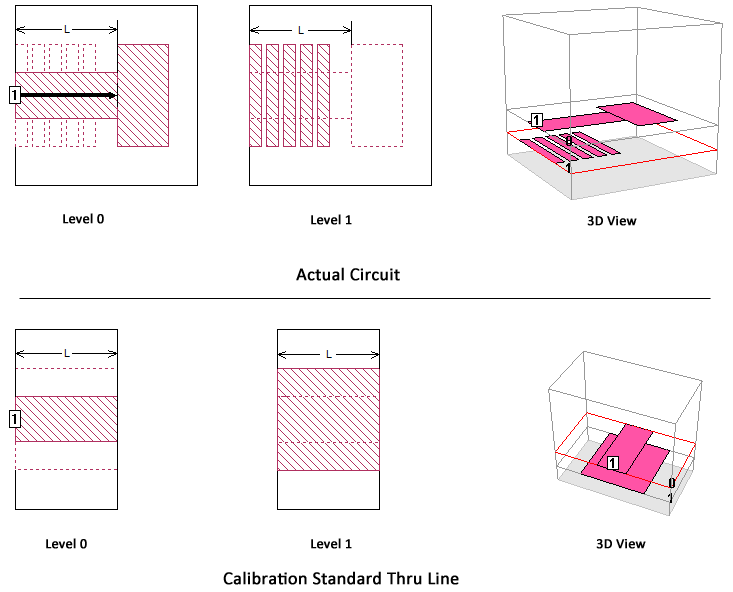
In the first example shown below, there is a single feedline on the box-wall, with no metal on another level. Therefore, the thru line upon which the calculation is based is reasonable and the resulting values are accurate.
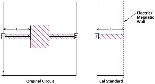
In the second example shown below, the circuit is more complex and the calibration standard thru line does not accurately reflect the actual circuit. Remember that the thru line used for the calculation is based on the cross section at the box-wall and is extended the length of the reference plane. In the actual circuit the metal on the level below the port only extends from the box-wall for a length much shorter than the calibration standard, but in the calibration thru line, this metal is extended for the whole length and the other metal polygons in the interior are completely ignored. These transmission line parameters will not be as accurate as the first example.
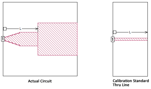
Z0 and Eeff are also not as accurate for feedlines with non-uniform width. Because the cross section is extended uniformly from the wall the length of the calibration standard, a feedline with a varying width is not accurately modeled when calculating the transmission line parameters, as shown below.