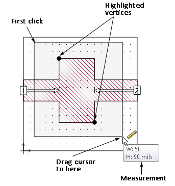
Selecting Edit - Measure from the menu or clicking on the Measure icon on the Edit tool bar opens the measuring tape which allows you to measure distances in your geometry.
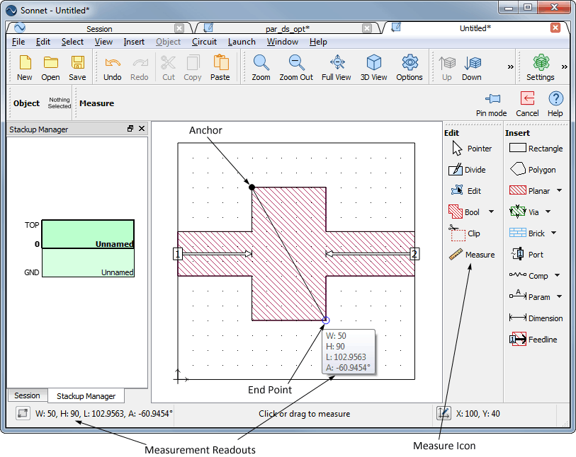
There are two ways to use the measuring tape, one is to drag the cursor until two vertices are highlighted. The distance between these two vertices is displayed in measurement pop-up. The measurement is also displayed in the status bar as illustrated in the second example.

The second method is to select an anchor point and measure using the anchor point as a reference. First, you click on an anchor point in your circuit. Once the anchor point is set, move your cursor to the desired location and the distance is displayed in the status bar and in a pop-up as shown below.

The measurement is displayed as the x delta, y delta, and straight line distance. The readout changes as you move the cursor. To reset the anchor, click again in your circuit, then select a new anchor point. As you move the cursor, different symbols appear to help in navigation. A blue square indicates a vertex, and a blue triangle indicates the mid-point of a polygon side. A dotted line extending from the anchor to an X where the cursor is presently located indicates that those two points are aligned in either the X or Y direction.