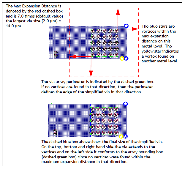
This control helps define the size of the resulting simplified via by allowing it to be larger than the original via array perimeter (also referred to as the bounding box). The default value is 7.0, which allows the simplified via to expand outward by a factor of 7 times the largest via size in the array. The advantage in expanding the simplified via is that it can often be sized to match the polygons to which the via attaches. Having the via polygon edge and pad polygon edge in alignment can significantly reduce the subsection density in the region and thereby reduce the memory requirement of the model.
An example is shown below. The algorithm looks outward from an imaginary rectangle (bounding box) drawn around the perimeter of the array (green rectangle). The distance checked out from the perimeter is the Max Expansion Distance (shown in red arrows). It is equal to the Max Expansion Coefficient times the largest sized existing via in the array. If a vertex from a pad polygon is encountered within this window (red rectangle), the expansion stops and this sets the simplified polygon edge. If no vertices are found in a particular direction, the edge of the simplified via rolls back to the existing via array perimeter. Please note that all metal levels are examined when looking for vertices within the maximum expansion distance.

 The default setting for Max Expansion Coefficient is 7.0. If you wish the simplified via to be the bounding box around the array, set the Max Expansion Coefficient to 0, which allows no expansion.